Conventional Systems VS Trunked Systems
02 Sep. 2016 Information
Conventional Systems
Simplex
In simplex operation one terminal of the system transmits while the other terminal receives. Simultaneous transmission and reception at a terminal is not possible with simplex operation. The simplex dispatching system consists of a base station and mobile units, all operating on a single frequency. Simplex operation is sometimes referred to as single-frequency simplex.
Half Duplex
In half-duplex dispatching systems, the base station and the mobile transmit on two different frequencies. The base station transmits on the mobile’s receive frequency and vice versa. However, the half-duplex terminal equipment does not allow simultaneous transmission and reception. Half-duplex operation is sometimes referred to as two-frequency simplex. Half-duplex configuration was designed to allow a repeater-type of operation, when a base station "repeats" and amplifies a mobile’s signal on a different frequency. Half-duplex operation is used most commonly in public safety LMR systems.
Full Duplex
In full-duplex operations, radios can transmit and receive simultaneously. As in half duplex, this operation uses two frequencies, the difference is that transmitter and receiver can be both powered and active full time. Repeater base stations typically operated in full-duplex mode, receiving on one frequency and re-transmitting the signal on another frequency, using separate transmit and receive antennas. For full-duplex single-antenna configuration, additional equipment is required such as duplexer, which enables the receiver and transmitter to use the same antenna simultaneously. LMR systems rarely use this type of operation, since full-duplex subscriber units are typically much more expensive and, if battery-powered, consume more battery power.
Trunked Systems
At the present time the land mobile frequency spectrum is very crowded and additional frequencies are difficult to obtain. For this reason there has been a great deal of work in developing new techniques to conserve spectrum.
Trunking is one of these conservation systems. Trunking is the commonly accepted term for electronically controlled sharing of a relatively small number of communications channels among a relatively large number of users. In general terms, a trunk is a shared voice or data traffic path between two points. Trunked systems use access control schemes to share channel capacity among many users. The electronic control enables users to take advantage of the fact that some transmitted channels are idle at a particular time while others are busy. This results in a more balanced load sharing between trunks. This is in contrast to a non-trunked or conventional system, where the users exercise their own coordination regarding access to system resources, by listening for idle time and making manual channel selections, which may result in unbalanced channel loads.
Trunked architectures differ by implementation of the system’s control logic. There are two main types of trunking architectures: dedicated control channel (centralized trunking by FCC definition) and subaudible signaling control (decentralized trunking).A combination of the two is also used in some systems.
In a dedicated control channel system (centralized trunked system), the system controller is the centralized logic of the system. It communicates with the units by way of the control channel. All other channels act as repeaters for communications between user radios. When user radios are not communicating, they continuously monitor the control channel. When a user radio needs to communicate, it sends out a channel request on the control channel. This request includes the ID of the talk group with which the radio wants to communicate. The system controller checks whether a vacant channel is available or not, and sends instructions to units on the control channel.
This type of trunked architecture typically places blocked calls in a queue to wait for a vacant channel thus minimizing lost calls. Typically, a first-in-first-out queuing principle is used. As soon as a channel becomes available, a queued system signals it to the user radio. To assess traffic load performance of a system of this type, the Erlang C model is typically used, which calculates the average delay in queue.
The typical trunking system consists of some type of access control (whether in each mobile unit or centralized at a base station site), switching equipment, system management computer, control and voice channel repeaters, modems, and telephone interconnect as illustrated in the following figure.
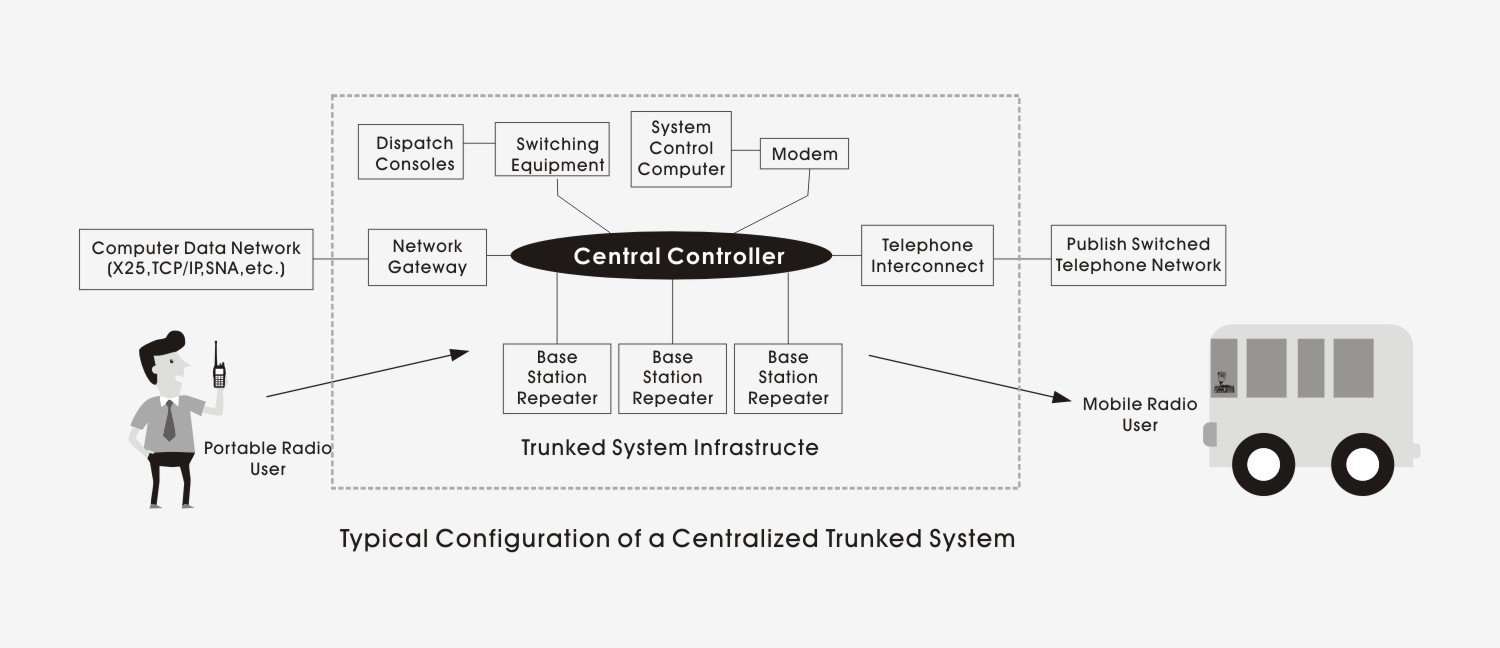
Centralized trunking uses a microprocessor that governs all of the base station repeaters after receiving and processing service requests over the control channel. The switching equipment provides the interface between dispatch consoles and the central controller. The system computer allows computer access and monitoring of the central controller. In addition, trunking systems can be programmed to include specific options depending on the user’s needs. Talk groups, encryption, emergency (e.g., man-down) operation, and telephone access are examples of some of the programming options.
A typical operational pattern of control channel trunking is as follows: User A wants to contact all of the units in his or her talk group. The Push-to-Talk (PTT) is keyed, which causes the radio to send a short burst of data to the control channel repeater. This data identifies the caller attributes and enters a channel request to the system controller. User A’s radio then switches to receive mode to await a data response from the controller. Upon receipt of the request, the system controller attempts to select an available voice channel. If a voice channel is available, the system controller sends a data message over the control channel switching all unit sin User A’s talk group to the available voice channel. Only units in this particular talk group are automatically switched to the assigned channel. When User A starts talking, all the members of the talk group will hear the conversation. This preempts any other use of that assigned channel for the duration of the call.
Trunked systems with subaudible control signaling, also known as scan-based or decentralized trunked systems, do not require a separate control channel and all channels can be used for communications between users. Each user radio monitors subaudible control data transmissions from its home channel continuously when it is not engaged in communications with other users. A home channel is one of the repeater transmit frequencies to which a particular user radio is assigned. The control information received subaudibly tells user radios what channel they should switch to if they need a channel to initiate communications or receive a call. It also tells them if all channels are busy. If a user attempts to initiate communications, he or she will hear a busy tone.
The logic in this system is distributed among each of the repeaters. A data bus connecting all of the sites updates the logic of individual sites to reflect which channels and sites are active and which are vacant. In this way, the system can operate without a system controller. The logic at each repeater can control those user radios for which it has a home channel. User radios are constantly advised of data relevant to the initiation and reception of communications. This design is usually limited to 15 channels. In trunked systems with subaudible signaling, blocked calls are usually lost rather than being placed in a queue to await a vacant channel. The user must attempt to initiate communications later. To assess traffic load performance of a system of this type, the Erlang B traffic model is typically used, which calculates the probability of lost calls.
Modes of Trunking -Either type of trunked system architecture, control channel or subaudible control, has the capability to perform message or transmission trunking. Message-trunking mode, which is also called conversation trunking, uses a delay timer (hang time), which allows traffic an uninterrupted repeater (communication channel) for the entire conversation between several users. In a system operating in transmission-trunking mode, the repeater channel is relinquished immediately after each user releases the key of the radio during an ongoing conversation (no hang time). Subsequent transmissions within the same conversation are transferred to another repeater when the second party keys his or her radio. Message-trunking mode provides greater channel availability for the user, while transmission trunking provides a greater channel availability for the system.
A third mode of trunking is a technique called quasi-transmission trunking. This technique holds a channel open for about one second after the last user de-keys the microphone (short hang time). Quasi-transmission trunking mode does not hold the channel as long as message trunking after the microphone has been de-keyed. This should result in fewer times when the repeater is unavailable to other users. At the same time, the channel is held long enough for users to keep the channel if they respond quickly (in less than one second) to each other’s transmissions.
Users do not manually select individual radio channels in a trunked system, unlike the procedure in a conventional system. Instead, they select talk groups, by performing essentially the same physical action of setting a knob to a different number. Each user radio is affiliated with at least one group and/or subgroup and has an individual ID. These groups may be called fleets and subfleets, or announcement groups and talk groups, depending on the manufacturer of the particular system. When a member of a talk group initiates a conversation, the trunked system controller automatically allocates one of the free radio channels to that talk group. Each radio in the talk group is automatically tuned to the allocated channel for the duration of the transmission without the user’s involvement.
Although initial trunked systems utilized the 800 and 900 MHz frequencies, in February1997, the Commission adopted a Second Report and Order, which allows some centralized trunking in the shared private land mobile radio bands below 800 MHz. The FCC now allows trunking on frequencies below 800 MHz if certain requirements are met (see Section 5.19), including the 150-162 (high VHF), 421-430 (UHF), 450-470 (UHF), and 470-512 (UHF-T) MHz bands. The rules adopted in the Report and Order became effective October 17, 1997. For most government and private users in the VHF band, commonly referred to as the public safety pool and the industrial/business pool, trunking is not a common feature, since its implementation was only approved so recently.
(Source:
Comparisons of Conventional and Trunked System)

